Introduction
Are you sick and tired of using a tooth pick to apply solder paste? Are you still using through hole components because you don’t want to deal with soldering surface mount devices (SMD)? If so, this post provides you with guidelines for building your very own laser cutter for cutting PCB stencils. With a total cost of approximately $200 (it can be significantly less if you already have parts laying around), this project can pay for itself very quickly. While you can get “low cost” stencils for your PCBs, they still can be quite expensive if you are only creating one or two boards.
The laser cutter can cut very accurate stencils from adhesive backed black vinyl sheets (on Amazon) for ICs with a pitch of 0.5mm (SON-10) and 0402 resistors (and possibly even smaller parts). These stencils are disposable and so cheap that you do not have to worry about using your stencils on one or two PCBs.

It gets better. You can use your RepRap as a laser cutter. All you need is a laser, a laser driver circuit board, and updated firmware (see below). While I built my laser cutter to be a laser cutter and not a 3D printer, I still used the RAMPS for the electronics even though it was built for the RepRap.
Before going onto how I built the laser cutter, I want to give you a quick overview of the design flow once everything is up and running:
- First, I create a circuit board and order it from either Seeedstudio or OSHPark.
- Next I make sure I have all the components I need. I personally prefer ordering from Mouser.
- Once the boards arrive, I export the gerber files for the stencils from Eagle CAD using a simple CAM processor.
- I then run a custom Python script which reads a gerber file and outputs a G-code file that the RAMPS electronics can understand.
- Using pronterface (a RepRap interface software), I control the laser via G-code creating the stencil
- A few minutes later, a perfect stencil has been created!
- Using a credit card or razor blade I apply solder paste to the board.
- I then manually place the parts using tweezers (sadly I do not have a pick and place machine…. yet).
- Finally, I carefully place the populated board in my toaster oven reflow oven.
- Approximately 5 minutes later, a perfectly soldered surface mount PCB is ready to be tested!
It has literally never been easier to build a custom circuit board. One of the best parts of this project is that most of the software needed was already written. This makes it VERY easy get going once the build is complete. Never reinvent the wheel if you can help it! That being said, you can buy a cutter/plotter for $200 on Amazon and make stencils that way. I believe that I will be able to achieve significantly higher accuracy with no software magic using my custom laser cutter. This is a much “simpler” alternative that may not provide as good results for approximately the same price.
Parts
The Build
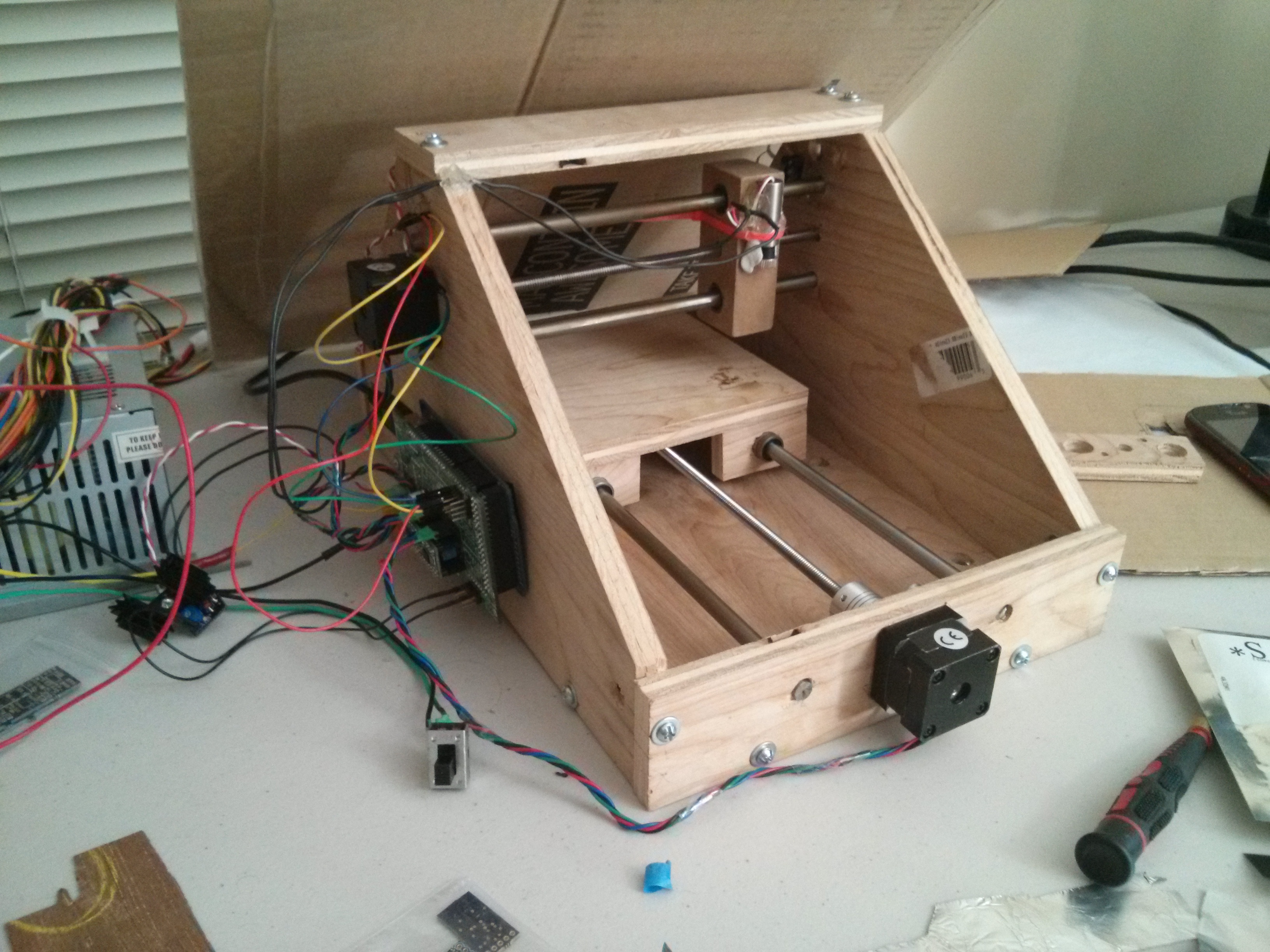
While I can give you a full parts list, I do not believe that it is necessary. I built my frame out of birch. In hindsight, I should have used a different material such as plexiglass or metal. After I was finished, Adafruit started releasing parts which would have made the whole processes so much easier. Check out their CNC category and use them to build a two axis device. That is what I recommend if you are starting from scratch.
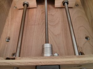
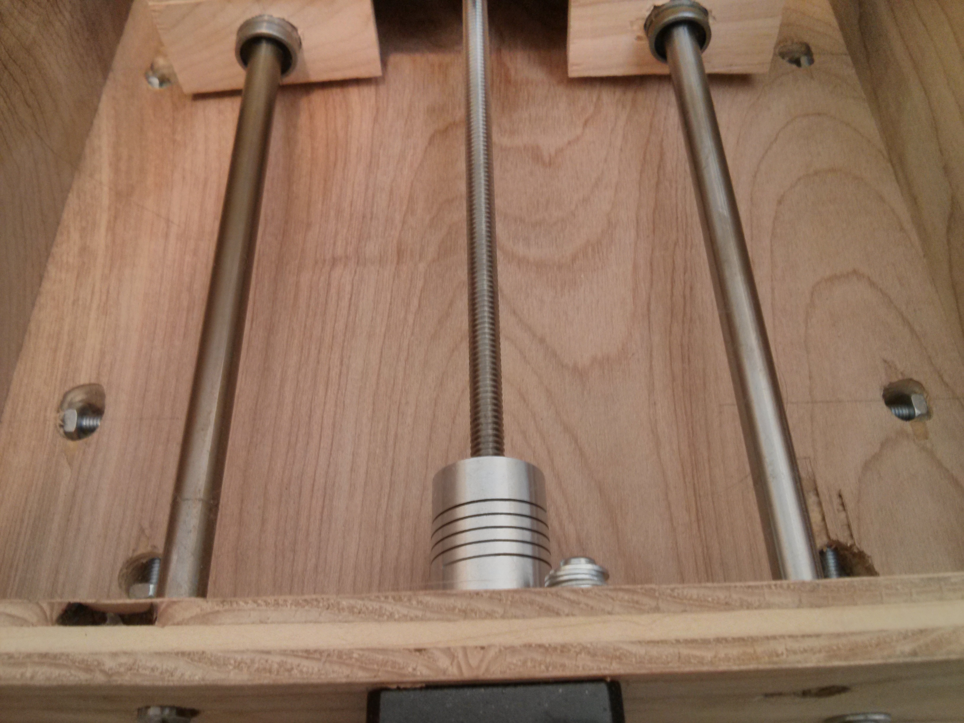
Where do you buy parts? Lowes, Home Depot, McMaster. It does not really matter, just make sure everything fits together nicely. For my device, I used 8mm smooth rods and 1/4″ threaded rods for both axis. I learned a lot from when I built a RepRap a few years ago (sadly, I sold it, otherwise it would have been the base for my laser cutter), which made the whole process a lot easier.
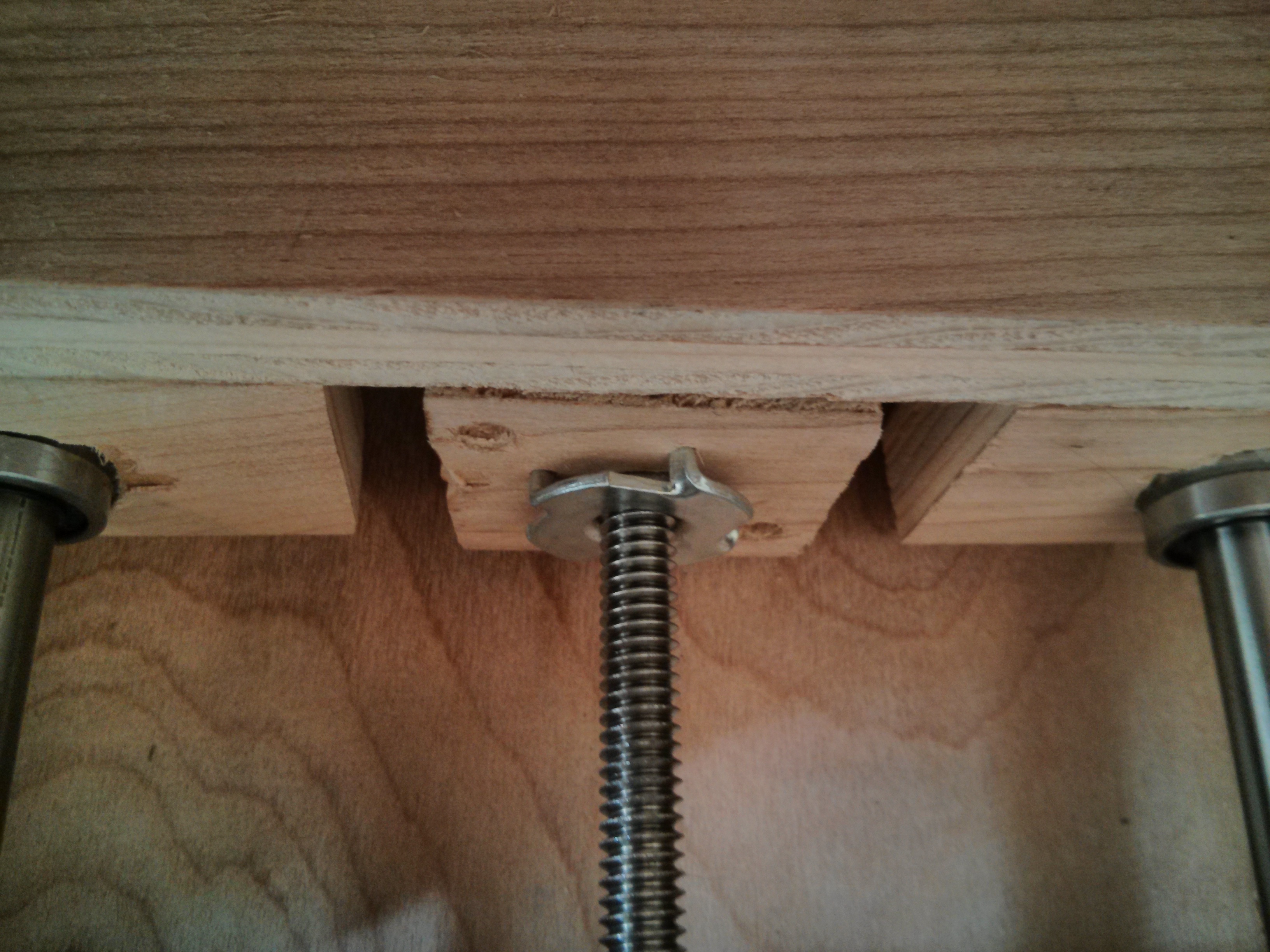
One trick which I will share with you, is what to use for the drive nut. Sure, you can spend tons of $$ for ACME rods and anti-backlash nuts, but I do not think that it is necessary. In Lowes (and I assume Home Depot), they have whats called a “Tee Nut”. I used the pronged version since I just hammered it into a piece of wood which was glued to each carriage. Get the longest one they have in stock that fits your threaded rod. The longer the nut is, the less backlash there will be. Spending less than $5 at Lowes sure beats spending over $50 on something you really don’t need.

I highly recommend buying your smooth and threaded rods from McMaster Carr and spending a bit extra money to get higher quality ones. While you do not need the best of the best, having high quality smooth rods can make all the difference.
As for the bearing and motor couplers, eBay is your best friend. See the list above for which ones I used. Make sure you buy linear bearings and flexible motor couplers. Also, make sure that your smooth rods are perfectly aligned in your frame, otherwise you will have problems. At the end of the build, you should have something with at least two axis. While you can use pulley driven carriages, they will not provide as much accuracy as threaded rod driven carriages.
The best source (in my opinion) for motors and motor drivers is Pololu. You really can’t go wrong with them. See the links above for which steppers and stepper drivers I used. An additional way to save money, is to buy NEMA-14 motors rather than NEMA-17 motors. As we are not building a large 3D printer, the extra power is not necessary.
Laser and the Laser Driver
The biggest difference between this and a RepRap is the laser (obviously). As such, you will need a laser and a circuit to drive the laser. The laser I used was the LPC-826, which can run up to 400-500mA and is widely available on eBay. I have found that you only need about 300mA (or even less) to make the perfect cut in black vinyl. This laser is available on eBay for about $10. If you have extra money in your budget, I highly recommend getting a blue laser or even a green laser rather than a red one. Why? Lasers with smaller wavelengths are better at cutting.
WARNING: IT IS VERY IMPORTANT THAT YOU ALSO BUY LASER SAFETY GOGGLES IF YOU USE A LASER IN ANY WAY SHAPE OR FORM. Looking at this laser can cause you to go BLIND. They don’t call it irreversible eye damage for no reason. Please, be safe. Do not attempt this project unless you know what you are doing, it can be very dangerous if you are not careful.
Once you have purchased your laser, be sure to pick up a focusable Aixiz module and glass lens. The glass lens will let you focus your laser better, creating thinner cuts. I have found that my stencil’s accuracy is not limited by the mechanical system or the electronics, but rather by the optics. My lens does not focus as well as it should which limits how thin my cut can be.
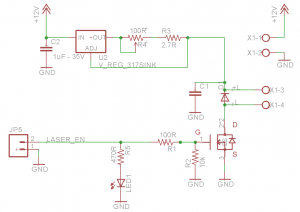
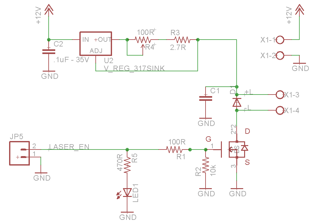
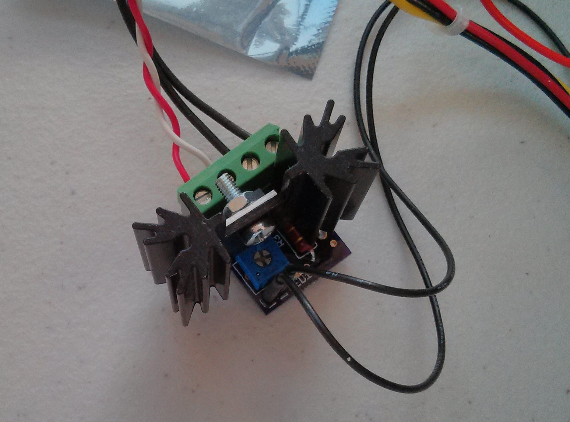
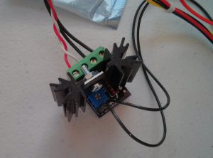
Laser Driver Schematic
This schematic is based off the LM317 and is in essence, a constant current source. The current output is controlled via a 100 ohm trimmer which has a 2.7 ohm resistor in series to limit the maximum current that can be sent to the laser diode. Additionally, the current source can be turned on and off via a MOSFET controlled by the Arduino. You really want to be careful with powering your laser diode as they can be blown very easily. The final circuit board is shown below. If there is enough interest, I will start selling the blank laser driver boards in the Hardware Breakout Store.
Electronics (RAMPS) and Firmware
As I previously mentioned, I use the RAMPS electronics which was originally created as an Arduino shield for the RepRap. Instead of using all three axis, I simply used the first two. Be sure to also hookup the endstops, I highly recommend that you use the mechanical ones rather than optical ones. I also did not populate any of the MOSFET drivers or thermistor parts. All in all, it was an easy and cheap build.
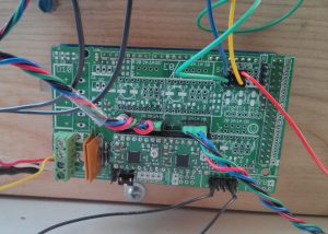
Partially assembled RAMPS electronics. This is all that is needed for the laser cutter.
To hook up the laser board, all that is needed is the AUX-2 header. This has the necessary connections needed to control the laser, an extra digital output (D42) and GND. Modifying the firmware proved to be just as simple as everything else. I simply needed to add a few lines of code for the laser to be supported via custom G-codes. I decided to use the code M52 to turn on the laser and M53 to turn off the laser. Place this code in the Sprinter.pde file at line 725:
|
|
// M52 Turn on LASER case 52: WRITE(LASER_EN, HIGH); break; // M53 Turn off LASER case 53: WRITE(LASER_EN, LOW); break; |
Be sure to calibrate your firmware as well by inputting the correct steps/cm into the configuration file. Please note, there are a few other changes that need to be made to the project. See the files list at the bottom of this post to download the Arduino project (RAMPS Laser Firmware). One final tip, use Arduino 0022. For some reason I had trouble with the newer versions when using the RAMPS firmware.
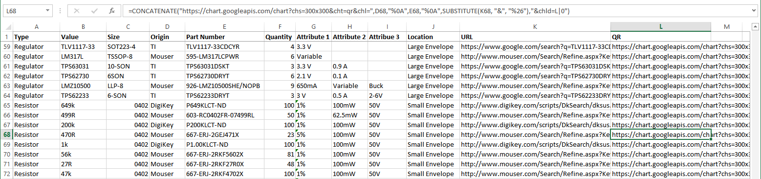
Software – Eagle Output and G-code
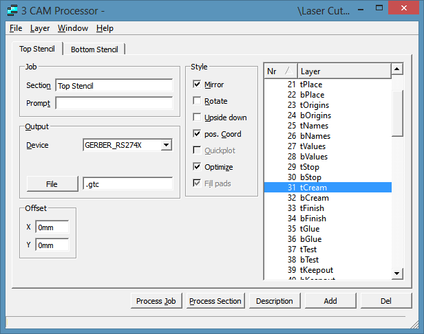
Here comes the most interesting part of the whole project. The goal is to make it as easy as possible to print stencils, in essence, I wanted only one step between Eagle CAD and usable G-code. First I use a CAM process to create a gerber file from the cream layers directly in Eagle CAD, this is fairly standard. The top layer must be mirrored for it it to work correctly.

To create the G-code I found some Python code which can convert gerber files to G-code, pygerber2gcode. While attempting to modify this code to convert gcode which the RepRap firmware would understand, I decided to gut the whole code and rewrite some of it. All the difficult parts were already completed in pygerber2gcode; all the credit for reading the gerber files goes to author of this project.
The modified code will read in a gerber file and output gcode to the specified file, which the laser cutter can directly understand. I am not a Python expert, so the code leaves a lot to be desired. It works just fine for me though, and I believe that it is structured in a way that allows it to be easily modified. In the future, it would be interesting to calculate the optimal size of the shapes to account for the material and laser used.
My code has been uploaded to github. Please feel free to modify it as needed!
Calibrating
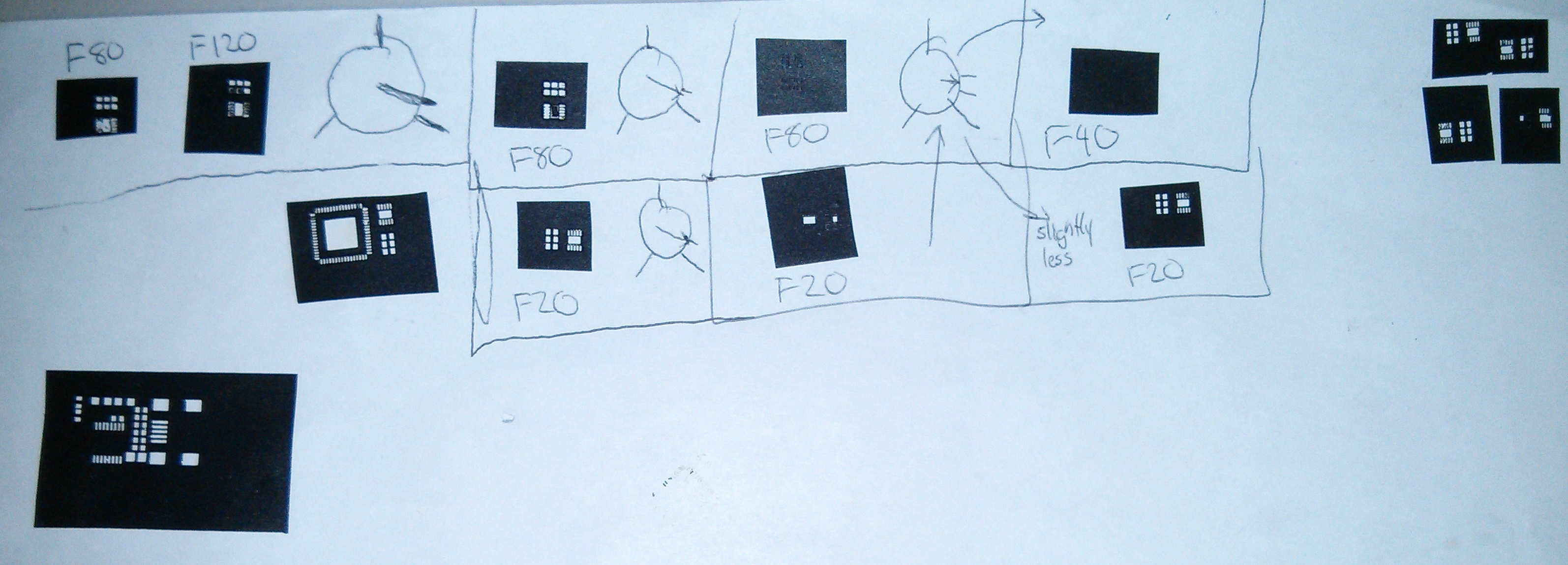
The most difficult part of this project was getting the laser cutter calibrated. This was difficult because you need to get the perfect balance between focus, power to the laser, and cutting speed to get the ideal cut. At first, I had the power turned up too high, this resulted in poor cuts due to the vinyl melting around the cut.
It turns out that the lens for my laser does not focus as well as I had hoped. This causes the laser to be wider than it is long, resulting in the cut being thicker in one direction than the other. Reducing the lasers power also helped minimize this issue. I ran quite a few tests to determine the best speed and laser current.
By taking the stencils and putting them on a white piece of paper, it is easy to see how well each cut was made. Be sure to keep track of your settings!
Results
Here are some of my results. I am VERY happy with how everything came out.

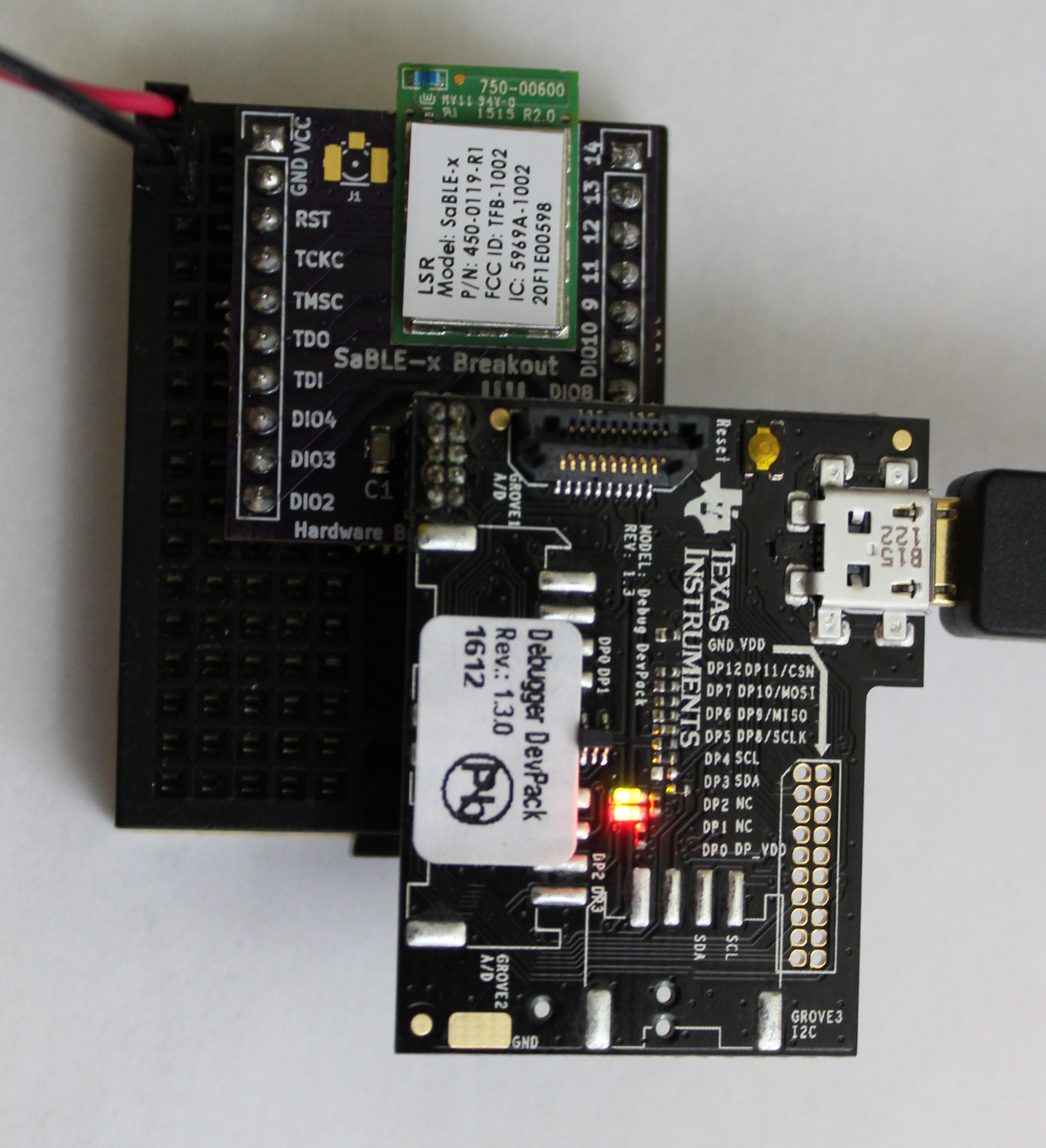
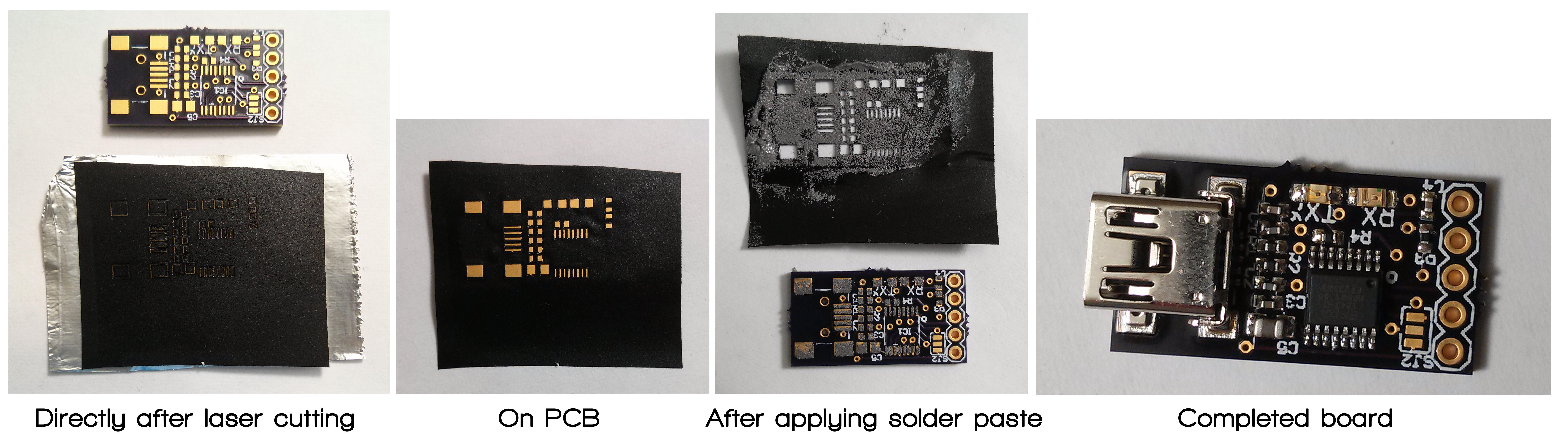
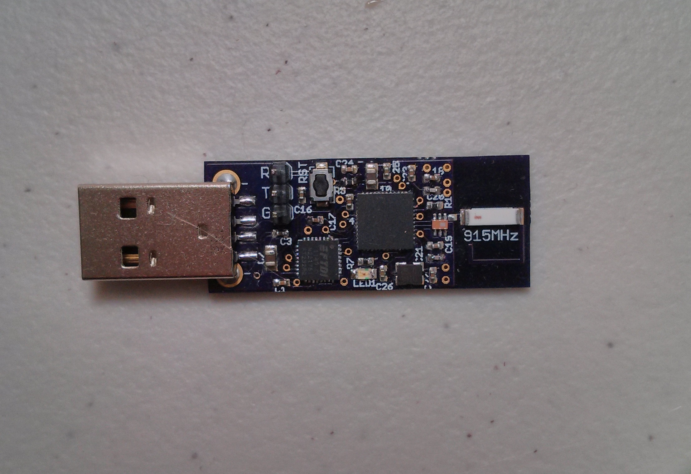
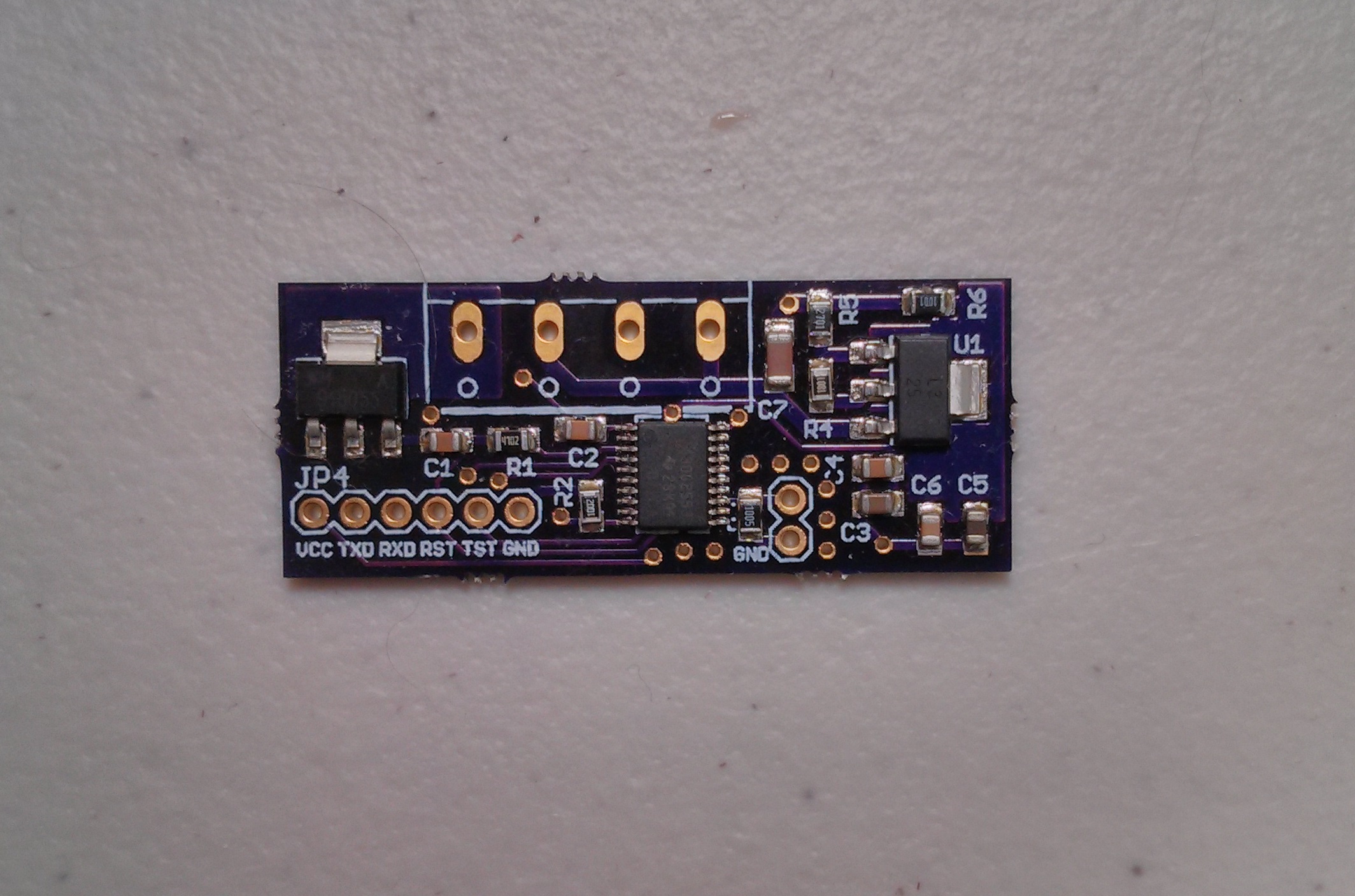
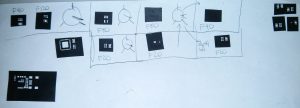
This figure depicts the steps needed to fully assemble a board. No touch ups were needed. The board was soldered in my reflow oven toaster oven. Be sure to click on this picture and zoom in so that you can see everything clearly.
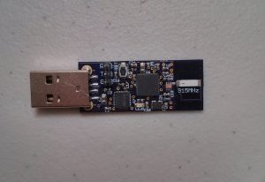
This is another board that used the laser cutter. It is a CC430 access point which uses the SON package from TI.
This is another example PCB that I soldered using a vinyl stencil from this laser cutter.
Concluding Remarks
I believe this to be a wildly successful project. While there is room for improvement, it works more than fine for my purposes. The most difficult part of the whole process is aligning the stencil on the circuit board. Check out github for all the files needed