
Relay Circuit and Breakout Board
Before continuing with our toaster oven “reflow oven” project, we should understand how relays work and how to build a simple relay breakout board. This post will discuss the design of a relay breakout board specifically for our reflow oven project.
Disclaimer: As I mentioned in the previous post, do not attempt this project unless you know what you are doing. High voltages are dangerous and can kill you. Do this project at your own risk! This part is especially dangerous, as we are dealing directly with high voltage signals.
Introduction to Relays
The goal of a relay is to control high power devices using low power signals. A perfect example is controlling a 1500W toaster oven with a 3.3V or 5V microcontroller. Another example would be using a microcontroller to turn on or off lights in your house/apartment/dorm. Although the two examples I just gave involve turning on or off AC power to a device, relays can also switch high power DC signals such as headlights on a car.
While there are many different methods you can use for switching AC devices, I will only mention three of them. The first method uses a triac, the second uses a solid state relay, and the third uses an electromechanical relay. The first two methods are solid state, which means there are no moving parts; there are many advantages to using these two methods. The downside of using a triac circuit, is that it is not trivial to build. The downside of using a solid state relays is that it can be very expensive compared to electromechanical relays.

Relay Internals (image from Wikipedia)
For this post, we will focus on electromechanical relays due to how easy they are to use and how inexpensive they are. Check out the Wikipedia page for a more detailed description of how relays work. To summarize, relays contains a coil (basically an inductor) which either forces a magnetic switch on or off; when current is flowing through the coil, the relay is “on”.
It is also important to note that relays won’t turn on until a certain amount of current is flowing through the coil. Many times, this current exceeds what a microcontroller can output so a transistor is needed to boost the current going into the coil.
Choosing a Relay
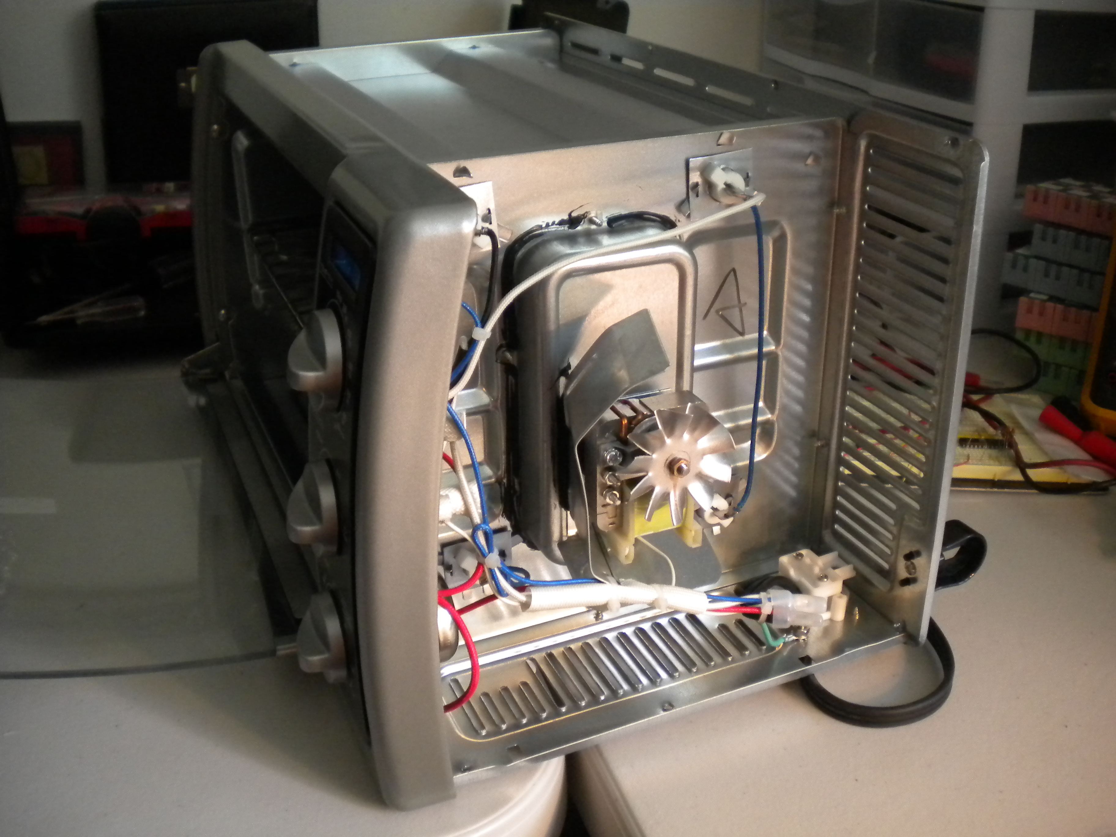
The first thing you need to determine when choosing a relay, is the maximum current and voltage you want the relay to control. For this project, my toaster oven has a maximum rated power of 1500W at 120V. It is important to find your maximum power, which is typically listed on every device. Using the following equation we can determine the maximum current the relay must switch on and off.
P = I * V
This is a very simple, yet useful equation; power is equal to current times voltage. Using this equation, the maximum current we need to design for is 12.5A. In engineering, it is always important to over-specify your system. Despite the fact that we only need to design for a maximum of 12.5A, we should design for 15A. This is a lot of current, way more than most devices will ever use. It is better to be safe than sorry!
Finally, the coil voltage and activation current must be determined. Since relays which can be turned on using a coil voltage of 3.3V or lower are expensive, we will be using a relay that has a coil voltage of 5V. This is great for those of you using a 5V microcontroller. Now that we know the coil voltage, we must find the cheapest relay which has the lowest turn on current. For my specific relay, this is denoted as “Operate power”. Given an operating power of 380mW and a voltage of 5V, the coil requires a minimum current of 76mA to turn on the relay. Since my coil requires more power than a microcontroller pin can drive, a transistor circuit will be needed.

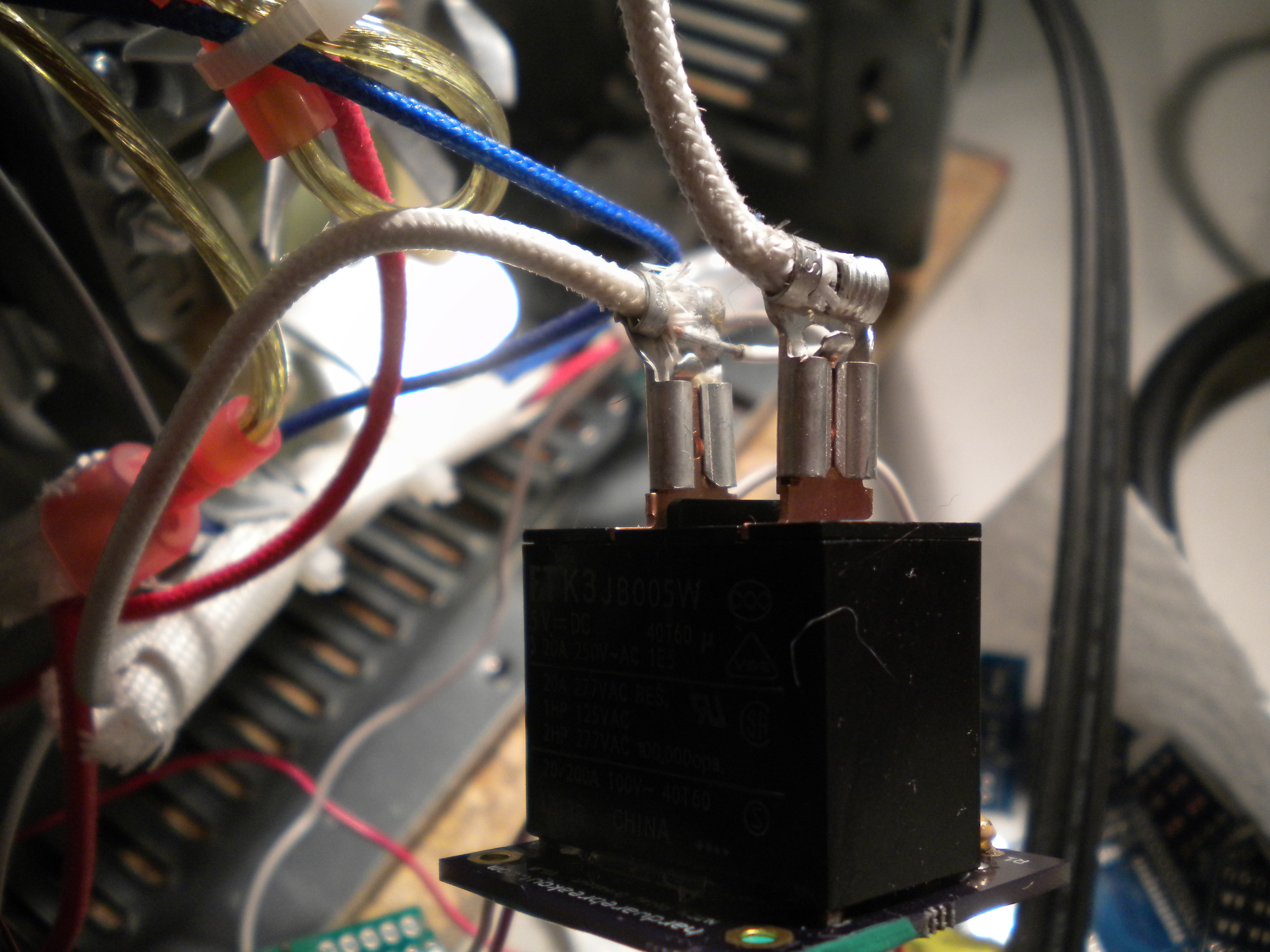
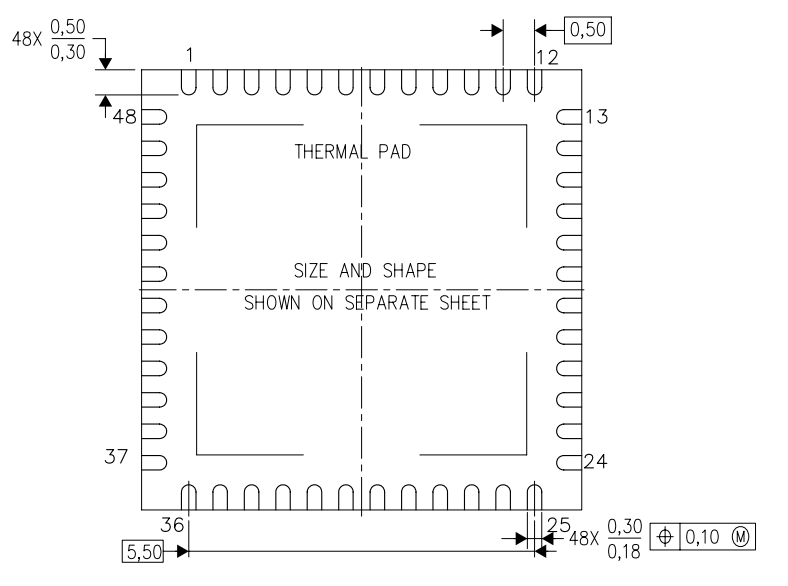
20A Fujitsu Relay with 250 tab connections.
Fujitsu Relay – 20A Heavy Load FTR-K3 Series
The last thing to note about the relay I have chosen, is that it is available with “#250 tab terminals”. As I mentioned in the previous post, this will greatly simplify things!
Relay Schematic
The image below shows how to set up a very basic relay circuit. The circuit consists of the relay, a diode, a MOSFET, and a resistor.
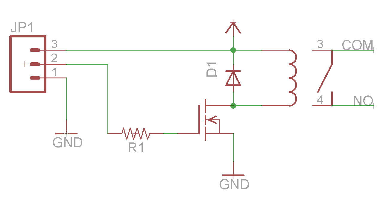
Schematic for the relay PCB.
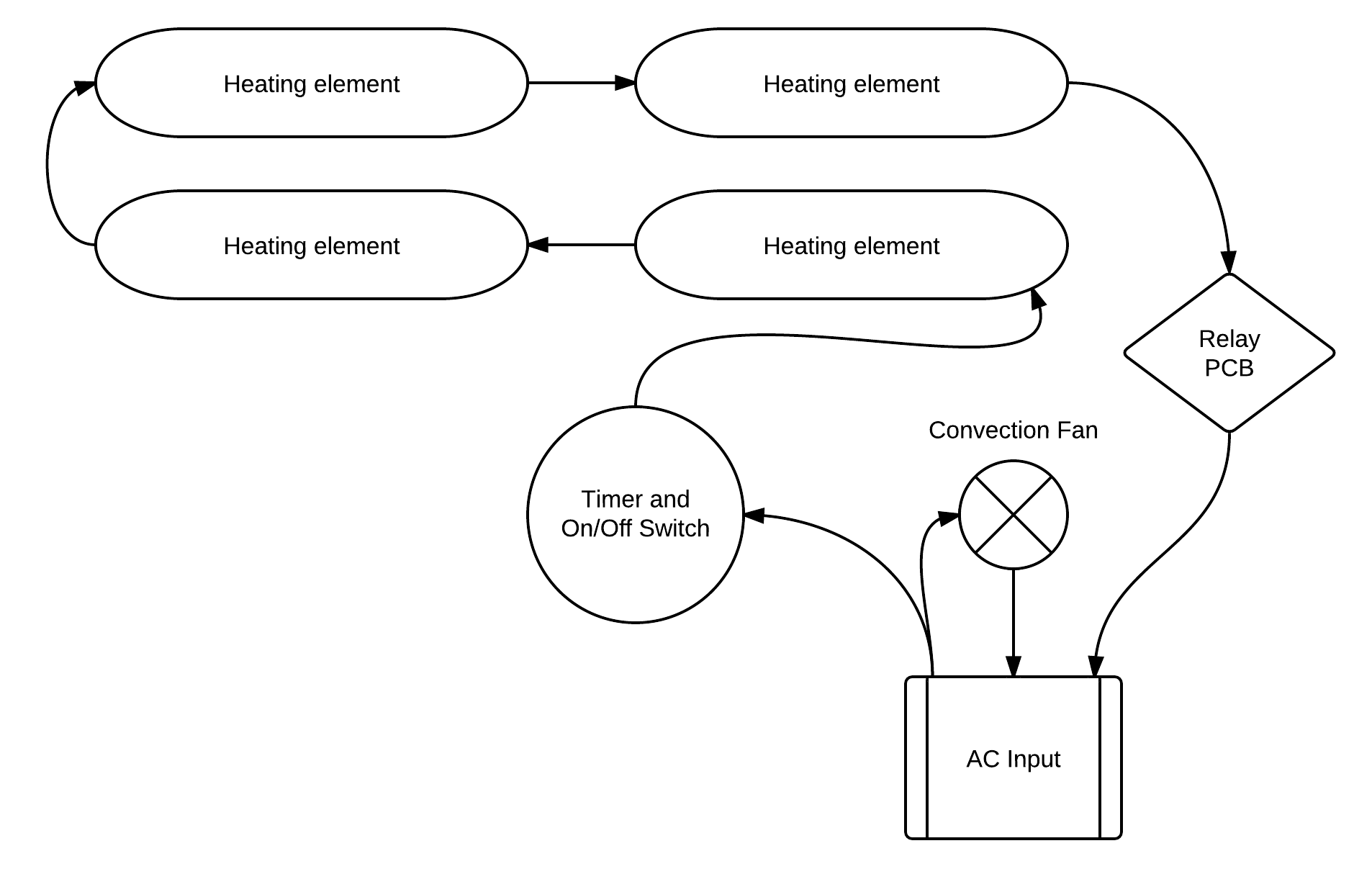
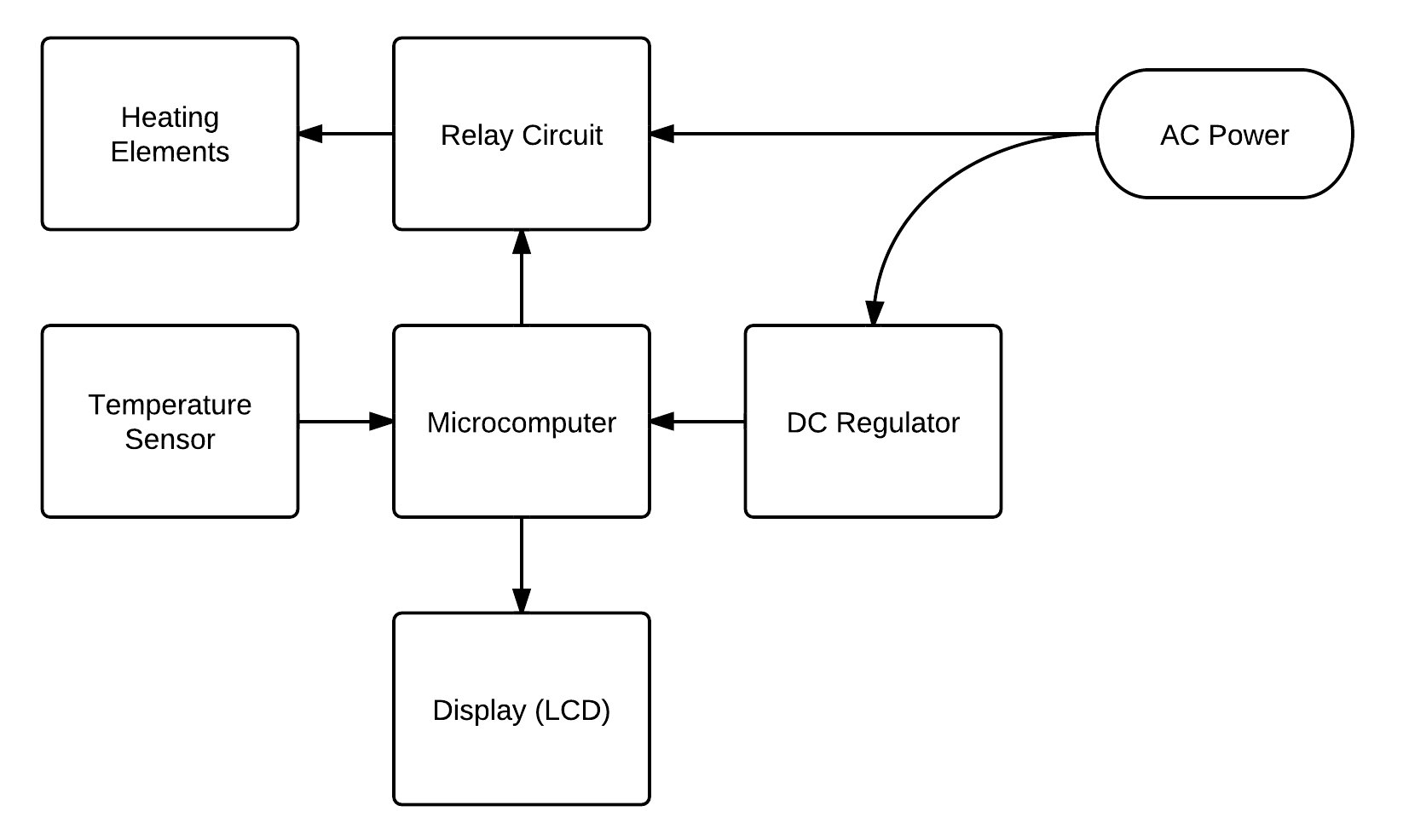
The output of the relay simply acts as a switch; for this project it will be hooked up between the heating elements and the AC return path (as discussed in the previous post) of my toaster oven. To protect the transistor (or microcontroller) from any unexpected current or voltage spikes, a protection diode is placed across the relay coil as shown above.
Using the transistor circuit shown above our MSP430 can turn on and off the relay. Since the output from a single I/O pin on the MSP430G2553 cannot exceed 6mA at 3V (we will be using 3.3V), a MOSFET (Metal-Oxide-Semiconductor Field-Effect Transistor) must be used instead of a BJT (Bipolar Junction Transistor). Simply put, a MOSFET amplifies voltage where a BJT amplifies current. Finally, in order to protect the MSP430, a small resistor is placed between the gate and the microcontroller (100 ohms).
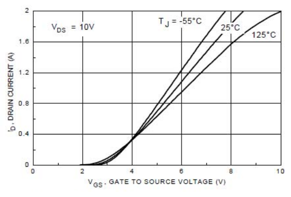
Current Voltage (IV) characteristic of a MOSFET.
Now you might ask, can we just use any MOSFET or DIODE? While almost any diode will do, the MOSFET should be able to output 100mA at 5V (for our specific relay) and should have a minimum turn on voltage of 3V or lower. How can you find out if your MOSFET meets these criterion? Check the datasheet. Always check the datasheet. The image above is an excerpt from the BS170D26Z datasheet from Fairchilds; this MOSFET is available on Mouser. Here you can see that the MOSFET can operate at about 150mA when the gate to source voltage is 3.3V.
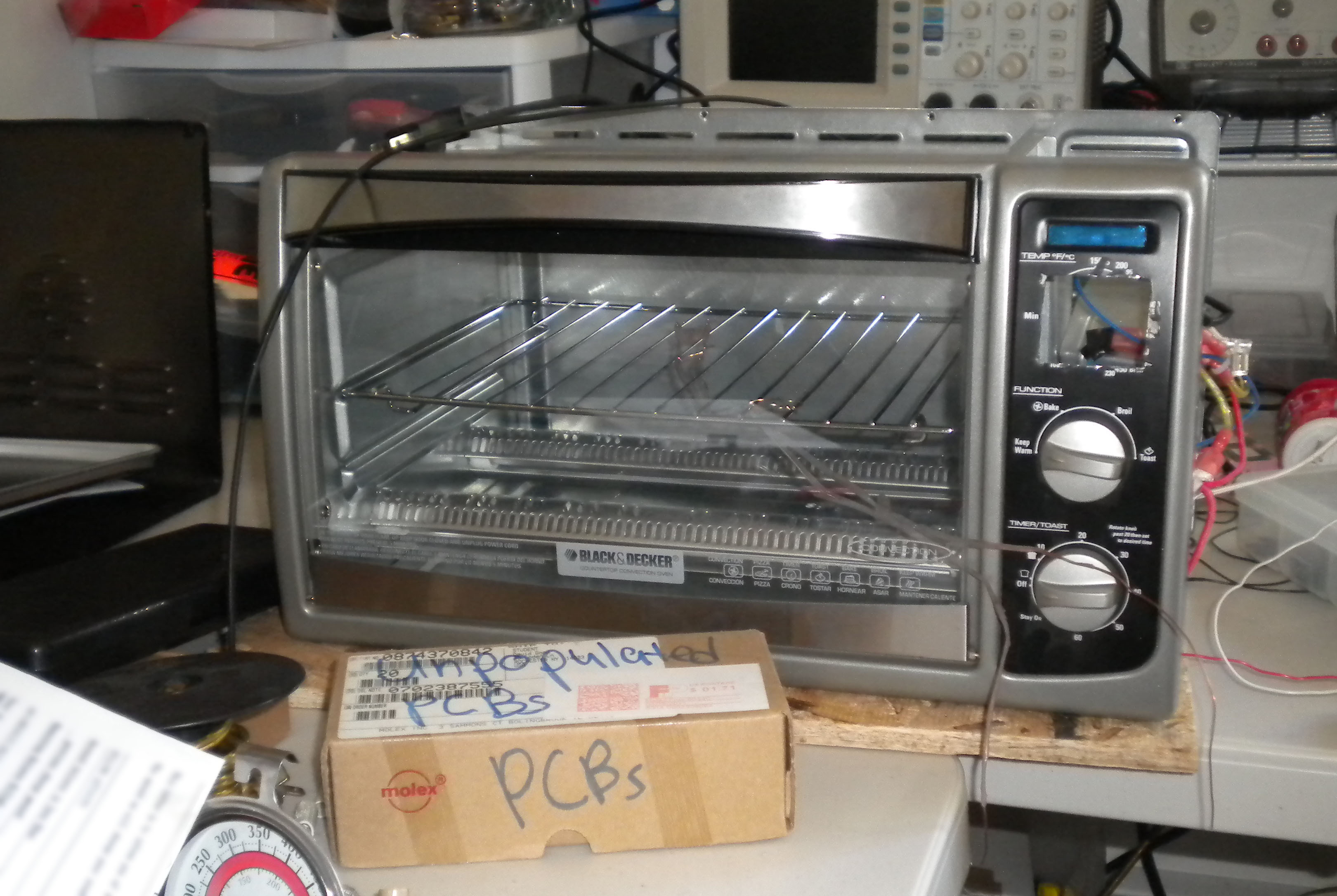
Putting the Circuit Together
When dealing with high voltages, it is important to be safe. As I keep mentioning, do not embark on this project if you do not know what you are doing. Due to safety issues, all relay circuits should be implemented on a PCB with thick enough traces to handle the current. Here is a picture of the circuit board I designed specifically for this project.
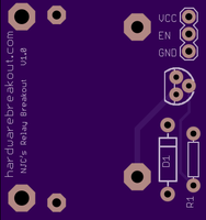
Rendering of my relay PCB from OSHPark.com (top).
This circuit board was made using OSHPark.com, a service which has evolved from Laen’s PCB group order. In my opinion, this service is the best for small projects where you need 3 copies or less of a 5 square inch or smaller PCB. Now all we need to do is solder up the circuit board and test it out. The board works great turning on and off my toaster oven!
Conclusion
Stay tuned for more posts on building a toaster oven “reflow oven”. In the next post, we will look into measuring the temperature inside of our toaster oven. Stay tuned!