

Using a Thermistor
Now that we have modified our toaster oven’s wiring and created a relay PCB to control the toaster oven, we need a way to measure the internal temperature. Throughout the reflow process, it is possible for the internal temperature of the toaster to reach 300C, so it is important to ensure that the temperature sensor chosen can function up to 300C.
There are many different ways to measure temperature using a microcontroller. The three main options include a thermistor, thermocouple, or RTD (resistance temperature detector). Although the thermistor is not the most straight forward method for measuring temperature, it is the cheapest method. Many thermistors also have a maximum temperature of 300C. While, this is cutting it quite close, we will rarely need temperatures over 250C. This is why I have chosen to use a thermistor for my toaster over.
Choosing a Thermistor
Choosing a thermistor can be quite simple, but there are tons of options. I ended up using a thermistor I had left over from my RepRap build, but almost any will do (as long as it can handle the temperature range we need).
There are a few things you should know about thermistors before choosing one. A thermistor’s resistance changes based on its temperature. In addition to a the thermistor having a specified maximum and minimum temperature, a baseline resistance, and tolerance will be given. The baseline resistance given is the thermistor’s resistance at 25C. Note, the resistance will change as the temperature changes. For our application, the tolerance doesn’t really matter since we do not require our toaster oven to be perfectly accurate.
Once you have chosen a thermistor take a look at its datasheet, there should be a “truth table” showing the resistance for each temperature. I used this thermistor, but I actually recommend that you use this one. It is cheaper, and my thermistor has flexible leads which make it more difficult to work with.
Installing a Thermistor
Before describing how to measure an actual temperature using your thermistor, I want to discuss how it should be installed into your toaster oven. An important thing to consider when using a thermistor in a high temperature environment, is that solder cannot be used since it will melt. Additionally, most wires cannot handle such a hot environment. Sadly, high temperature wires can be somewhat expensive and many are only rated to 250C.
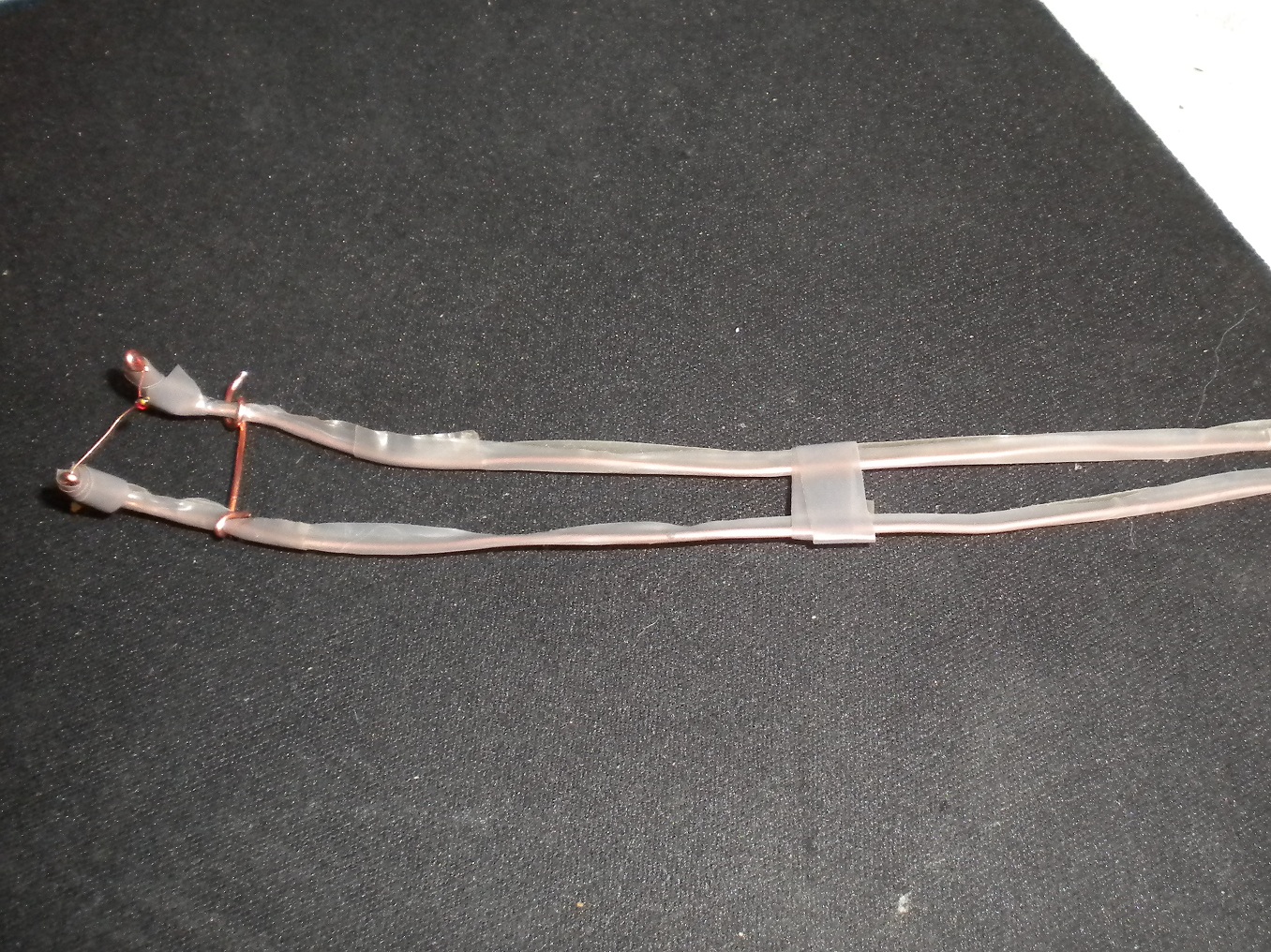
My thermistor hooked up to wires wrapped in PTFE tape (I ran out of Kapton Tape)
A [reasonably] cheap solution is to remove the insulation off of a solid wire and cover it with Kapton Tape so there are no shorts. Kapton Tape is a very high temperature tape which can prevent the wires from making electrical contact with each other and the inside of the oven, it is also used when building a RepRap extruder. Finally, we need a way to connect the thermistor to our makeshift high temperature wire. If you are using a thermistor with flexible leads, just wrap it around a bunch of times and them tape it up with the Kapton Tape. A better method for the thermistors without flexible leads, is to crimp the leads to the wire, just be sure to remove any plastic which can melt before installation.
Here are some pictures from my build. One last thing to note: you will need to drill a hole in the toaster oven’s interior for the thermistor wires to go through. Use a Dremel or a hand drill. Don’t forget to wear safety goggles!

Thermistor and wire assembly attached to the inside of my toaster oven.

The two holes for the thermistor wires.
Converting Resistance to Temperature
You are probably thinking, “Great! We have the thermistor installed, but how do we use it to actually measure temperature?” From a high level, we must convert a resistance to temperature. While you don’t necessarily need to do this, and you definitely don’t need to do it in MATLAB (or Octave), I highly recommend that you plot the table in your thermistor’s datasheet.
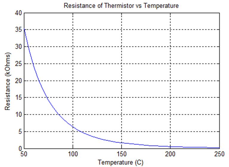
Thermistor resistance as a function of temperature.
Take a look at the higher temperatures (over 150C) and let’s assume that we can digitize that curve directly using an analog to digital converter (ADC), we still have a big problem; digitizing this curve would not provide us with enough accuracy in the most important temperature range. For example (hypothetically), an ADC value of 253 would represent 215C and 254 would represent 235C. Given that there always exists noise in any analog to digital conversion, we would not be able to accurately measure the temperature over approximately 100C.
To fix this problem, we somehow need to make the resistance change more uniformly over higher temperatures, like the lower temperatures currently do. This will correspond to a higher accuracy when digitizing the signal. Typically, the first step to measuring resistance is to convert it to a voltage. The easiest way to do this is to use a voltage divider.

Image from Wikipedia
Vout = Vin*R2/(R1+R2)
Choose a resistor, use this equation, and then plot the voltage against temperature. We still have the same problem, when converted to digital the higher temperatures will not have enough resolution. I have a simple solution. It is out of the scope of this blog post for me to explain how I decided to use this method, so I will just give you my solution.

The circuit I used to transform the thermistor’s resistance into voltage.
Req = 1/(1/Rtherm + 1/R3)
Vtemp = Req/(R2+Req)
Simply use the above equation to convert the thermistor resistor to the voltage on “TEMP”. Req is the equivalent resistance of R3 in parallel with the thermistor resistance Vtemp is the voltage at signal “TEMP”. Don’t worry about the capacitor, that is only there to keep transient spikes to a minimum, it does not effect the final temperature measurement. You can then plot the results in either MATLAB, Octave, or Excel. One thing to note, is that Vtemp will most likely not be very large. You amplify the signal as needed, depending on what the voltage is at room temperature. This can be done using a non-inverting op-amp circuit. I used a voltage follower in order to buffer the signal that the ADC resistance does not affect the calculated resistance.
Additionally, you can convert the output voltage into an ADC value. Note how the curve is more uniformly spread out across all temperatures. Here is the result plotted via MATLAB:

Plot of the ADC value (for a 8-bit ADC) against different temperatures.
Looks great! Doesn’t it? Now all we need to do is create a lookup table (LUT) for our microcontroller. Any microcontroller will do. Instead of typing out each value, I generated the LUT array in MATLAB. The LUT takes in an ADC value and then spits out the correct temperature. Please note that this method will not be perfectly accurate and if you want better accuracy you will have to calibrate the sensor manually. When comparing my results to an oven thermometer, it is more than accurate enough for a reflow toaster oven. For your convenience, here is the LUT I used in my MSP430 code (build in Code Composer Studio). For more information on the MSP430, check out my other blog: NJC’s MSP430 LaunchPad Blog.
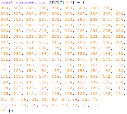
This is the thermistor LUT I used on the MSP430.
Conclusion
The method I used here to generate a LUT for our thermistor can be used with any sensor. MATLAB (Octave) is a great tool and is quite easy to use. Now that we can accurately read a temperature on a microcontroller, we are almost done with our toaster oven reflow oven project. All that remains is integrating everything together into one nice package and creating the control system, which will be done by the MSP430.
All of my MATLAB code is provided below. Please note that it is not very well commented, it is provided only as a reference. If you have questions about anything specific, please contact me or leave a comment.
Useful Links